7 min read
How to Test Potentiometer with Multimeter (6-Step Guide)
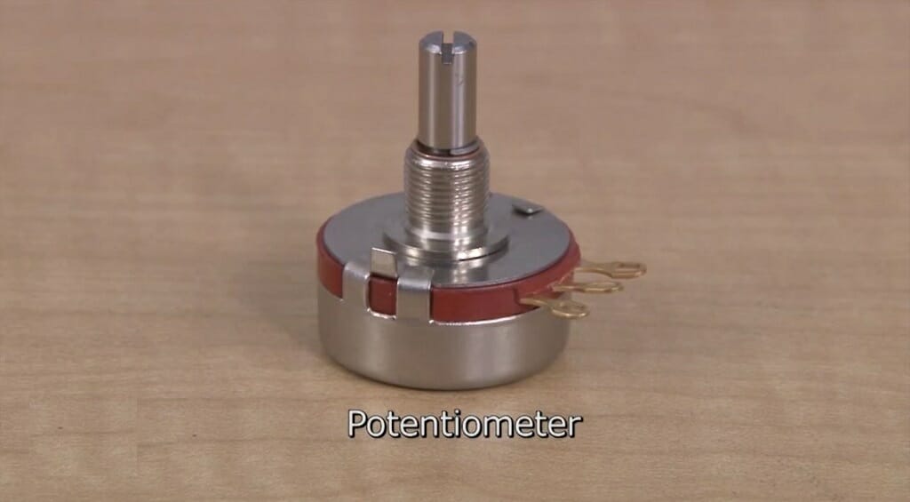
Potentiometers have many practical uses that can be pretty handy for controlling electrical devices. For instance, with the help of a potentiometer, you can control the volume of a radio, the speed of a toy, lighting levels, and much more. All of this is done by changing the resistance of the potentiometer. Sometimes, you might have to test the resistance of this device. That is why today, I’m hoping to shed some light on how to test the potentiometer with a multimeter.
To measure the resistance of a potentiometer,
- First, set the multimeter to measure resistance.
- Then connect two alligator clips to the red and black leads of the multimeter.
- Next, connect the other ends of the alligator clips to the potentiometer’s terminals.
- Compare the multimeter readings with the potentiometer’s rating.
Mechanism of a Potentiometer
Before starting the testing process, there are a few things that you need to understand. So, please don’t skip this section. If you are new to electrics, having a proper understanding of the potentiometer will definitely benefit you while testing the resistance.
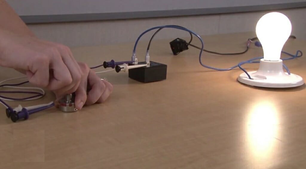
Usually, the potentiometer is used to control the resistance level. Imagine for a moment a potentiometer that has a rating of 1K. That means the particular potentiometer is capable of providing a 1000Ω resistance. So, you can apply this resistance to any electrical device by connecting the potentiometer.
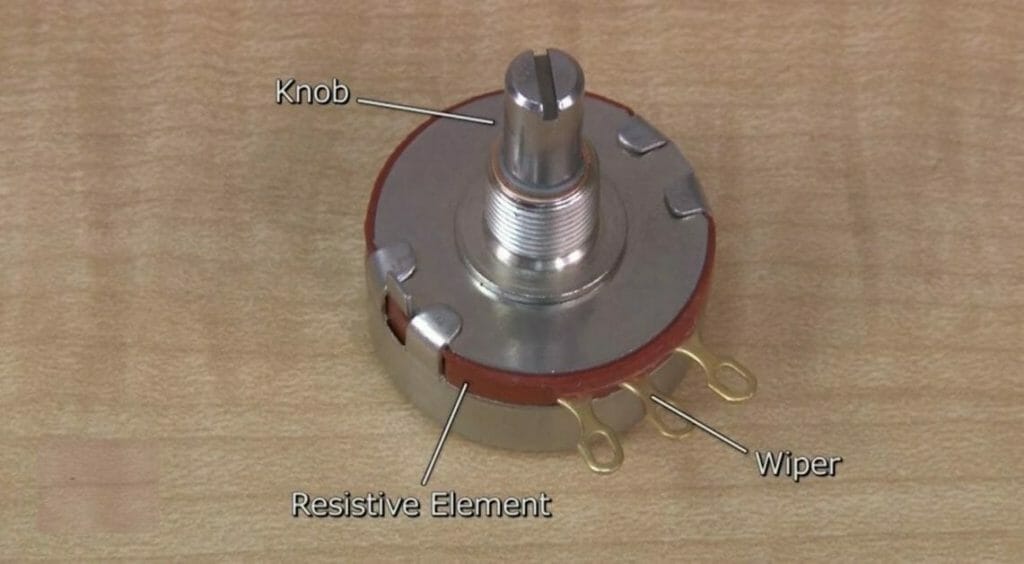
The potentiometer has three terminals and a controller knob. Among these three terminals, two terminals are known as ends, and the other terminal is known as the wiper. Two end terminals will give you the rated resistance. The wiper comes with an adjustable mechanism. So, you’ll be able to adjust resistance according to your need. Also, you can use the controller knob to adjust the wiper terminal’s location. Eventually, you’ll be able to control the output voltage or current.
RELATED Solar Panel Testing (3 Methods)
Process of Testing the Resistance of a Potentiometer
For this test, you’ll need the following things. So, make sure to gather them before jumping into the testing process.
Things Needed
- Digital multimeter
- Two alligator clips
- Potentiometer
Step 1 – Determine the Rating of the Potentiometer
The rating represents the fixed ohm value of the potentiometer. So, inspect the potentiometer for such marking. For instance, if you inspect closely, you can locate a 1K, 5K, 10K, or any other rating on the potentiometer.
For this demonstration, I’m using a 1K potentiometer. That means the potentiometer is capable of providing a 1000Ω value.
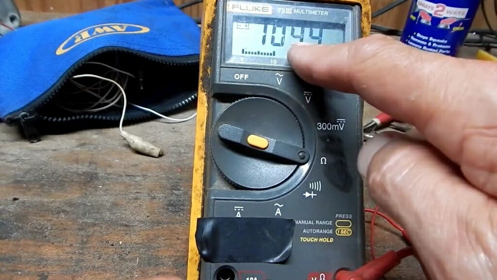
Step 2 – Set up the Digital Multimeter
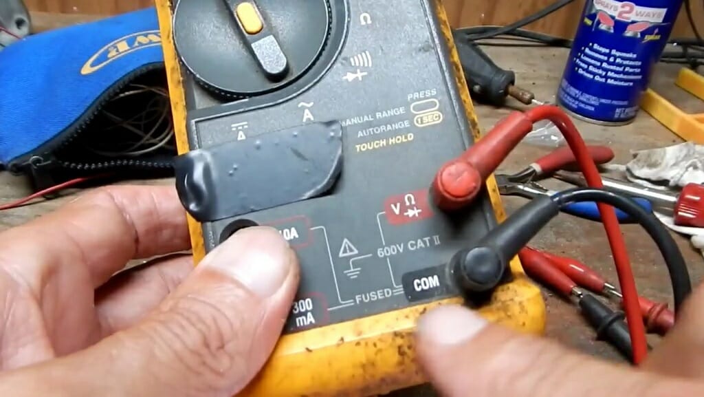
Next, get the multimeter and set it for resistance mode. If you are not familiar with the resistance settings, here is how you can do that.
First, insert the red jack into the Ω port and the blackjack into the COM port. Then, turn the dial to the Ω symbol. That’s it. Now the multimeter is ready for the test.
Keep in mind: For some multimeters, you’ll have to set the resistance range. If that is the case, set it to a value such as 10KΩ.
Step 3 – Inspect the Potentiometer Closely
Now, take the potentiometer and inspect it closely. There should be three terminals. You already know that a potentiometer is equipped with two end terminals and one wiper terminal. Before testing the resistance, you need to identify each terminal correctly.
Most of the time, the wiper terminal is the middle one, and the other two are the end terminals. You can confirm this by changing the resistance. You’ll get a better idea about that at the end of this testing process. For now, consider the middle terminal as the wiper which is connected to the controller knob.
Step 4 – Connect the Alligator Clips
Even though it is possible to test the resistance without alligator clips, you might find it difficult. For example, using alligator clips will free up your hands. So, you can freely rotate the controller with your hands. Otherwise, you’ll need another person to handle the controller while you are holding the multimeter leads on the potentiometer terminals.
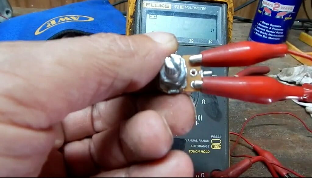
Now connect the multimeter leads and the potentiometer terminals using the alligator clips. First, you should test the end terminals. So, connect the alligator clips to the outer terminals (leave out the middle one).
Step 5 – Check the Reading
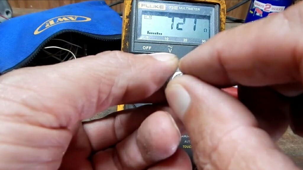
Then, check the reading. The multimeter should display a resistance reading close to 1000Ω. This reading shouldn’t change while you rotate the controller.
Keep in mind: In most potentiometers, you can expect a 5-10% tolerance. Because of that, the reading might range between 950-1050Ω. (1)
Step 6 – Test the Wiper Terminal
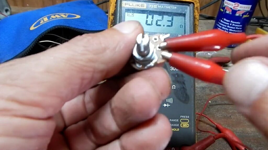
Next, disconnect one of the alligator clips from the end terminals and connect it to the wiper terminal. Now rotate the controller and inspect the multimeter reading.
If you follow the process correctly, the reading should change while rotating the controller. Don’t forget to check the minimum and maximum resistance using the controller.
Where Can I Find the Wiper Terminal on a Potentiometer?
In most potentiometers, the wiper terminal is located at the center. With the wiper terminal, you can change the resistance level to 10, 20, 30,40, or 50 percent. The wiper terminal is connected to the controller. So, when you turn the controller, the wiper terminal follows the same path.
Wrapping Up
The potentiometer is the best option for changing the output voltage or the current of electrical devices. However, for that, you’ll need a proper working potentiometer. So, check the resistance of the potentiometer with the above testing process. (2)
Take a look at some of our related articles below.
References
(1) tolerance – https://medium.com/illumination/the-secret-to-being-an-exceptionally-tolerant-person-a0872af504a5
(2) testing process – https://www.sciencedirect.com/topics/computer-science/testing-process
Video References
GalcoTV
Bill Eaglerunner