5 min read
How to Test a Stepper Motor with a Multimeter (Guide)
A stepper motor is a DC motor that can be “stepped” by a microcontroller and its main parts are the rotator and stator. They are used in drives, floppy disks, computer printers, slot machines, image scanners, CNC machines, compact disk drives, 3D printers, and many other devices of the kind.
Sometimes stepper motors get damaged causing the continuous electrical path to break. Your 3D printer or any other machine that uses these motors won’t work without having continuity. So, it is important to check if your stepper has continuity.
In general, you will need a multimeter to perform a continuity test on your stepper motor. Start by adjusting your multimeter. Rotate the selection knob dial to the ohms setting and plug the multimeter probes into their respective ports i.e. black probe to the COM section and the red probe to the port with a “V” next to it. Adjust your multimeter by pinging the probes together. Test the wires or the pins of the stepper rotator. Note the readings on the display unit.
Usually, if a conductor has a continuous electrical path, the readings will range from 0.0 ohms to 1.0 ohms. You will need to purchase a new stepper rotator if you get readings of more than 1.0 ohms. That means the resistance to electrical current is too much.
What You Need to Test your Stepper Rotator with a Multimeter
You need the following tools:
- A stepper rotator
- A 3D printer
- A stepper cable that goes into the printer’s mainboard – the coaxial cable should have 4 pins
- Four wires in the case of stepper rotators with wires
- A digital multimeter
- Multimeter probes
- Adhesive tape
Adjusting the Multimeter
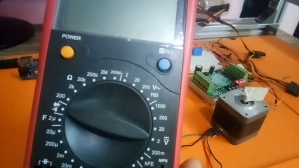
Start by selecting ohms on your multimeter using the selection knob dial. Ensure you have 20 ohms as your lowest. That is because most stepper coil resistances are under 20 ohms. (1)
Plug the probes into the multimeter ports. If the probes are not plugged into their respective ports, then plug them as follows: insert the red probe into the port with a “V” next to it and the black probe into the port labeled “COM”. After plugging the probes proceed and regulate them.
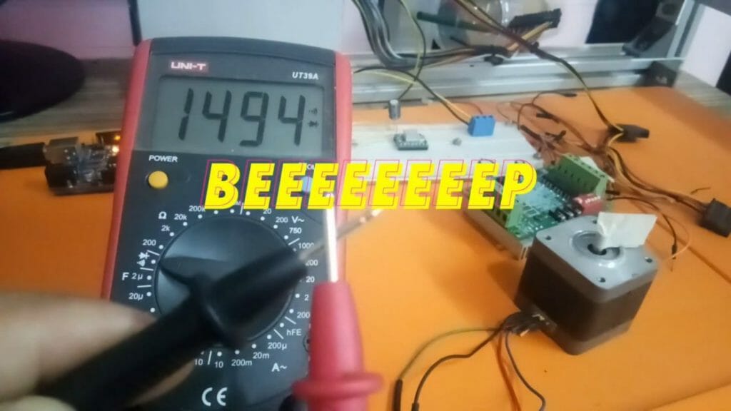
Adjustment of the multimeter will tell you if the multimeter is working or not. A brief beeping sound means the multimeter is in good status. Simply ping the probes together and listening to the beep sound. If it doesn’t beep, then replace it, or take it to a technician for repair.
Testing the Wires That are Part of the Same Coil
After you have your multimeter set, proceed to test your stepper rotator. To test the wires that are part of the same coil, attach the red wire from the stepper rotator to the red probe.
Then take the yellow wire and connect it to the black probe.
The multimeter will not beep in this case. It is because the yellow-red wire combination is not of the same coil.
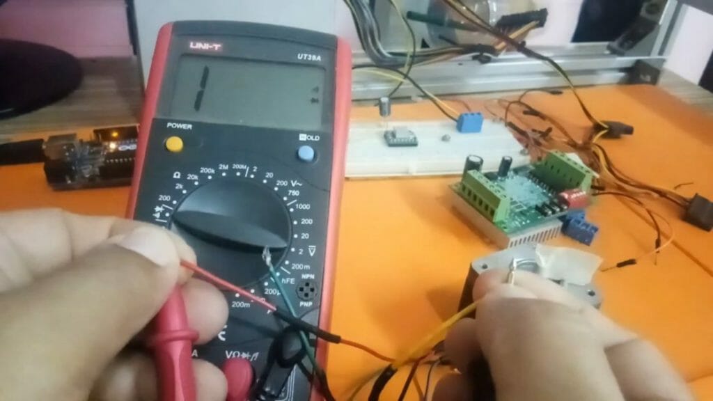
So, while holding the red wire onto the red probe, release the yellow wire and attach the black wire to the black probe. Your multimeter will beep continuously until you break or open the switch – by disconnecting the multimeter probes. The beeping means the black and the red wires are of the same coil.
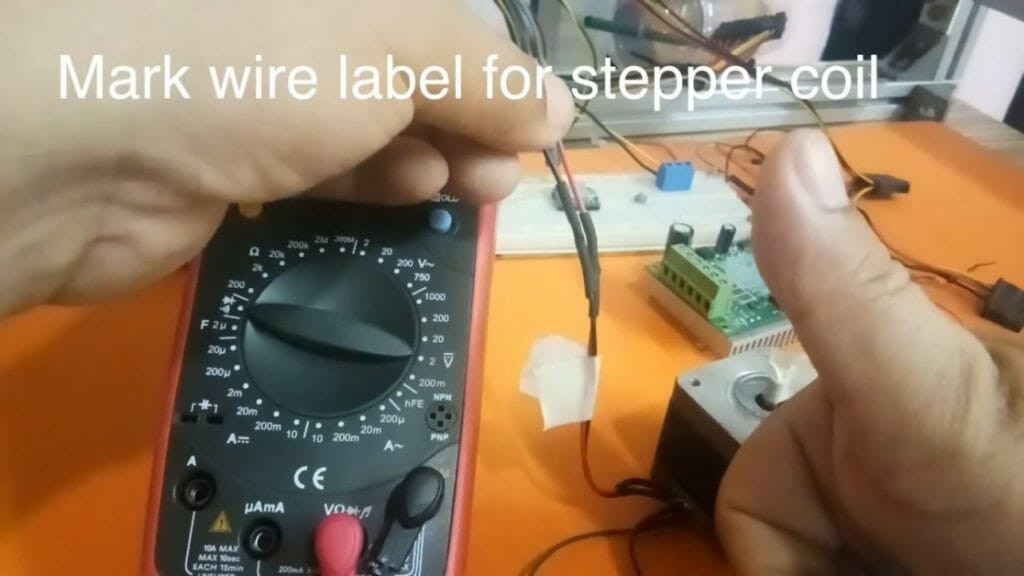
Mark the wires of the same coil, i.e. black and red, by attaching them using tape. Now proceed and attach the red probe to the green wire, and then close the switch by attaching the yellow wire to the black probe.
The multimeter will beep. Mark these two wires also, with a tape.
Testing the Pins in case of Pin Wire
Well, if your stepper rotator uses a coaxial cable, then you will need to test the pins on the cable. There are usually 4 pins – just like the 4 wires in the stepper rotator with the wires.
Please follow the outline below to perform a continuity test for this type of stepper rotator:
- Connect the red probe to the first pin on the cable and then the other probe to the next pin. There is no polarity so it doesn’t matter which probe goes where. Note the ohms value on the display screen.
- While holding the probe on the first pin constantly, move the other probe across the other pins stepwise, each time noting the readings. You will realize that the multimeter won’t beep or register any readings. If it does, your stepper needs fixing.
- Take your probes and attach them to the 3rd and 4th probes, note the readings. You should only get ohms readings across two consecutive pins.
- You may proceed and verify the ohms values of other stepper rotators. Compare the values.
Wrapping Up
When checking the ohms of other stepper rotators, do not mix the cables. Different steppers have varying wiring systems and that can damage other incompatible cables. Otherwise, you may verify the wiring, if the 2 steppers have the same wiring styles, then you use the cables interchangeably. (2)
Take a look at some of our related articles below.
- How to check continuity with a multimeter
- How to test spark plug with multimeter
- Multimeter CAT ratings
References
(1) coil – https://www.britannica.com/technology/coil
(2) wiring systems – https://www.slideshare.net/shwetasaini23/electrical-wiring-system
Video References