7 min read
How to Wire a Power Distribution Block (8-Step Guide)
In this article, I’ll teach you how to wire a Power Distribution Block (PDB) to distribute electricity from a single input source to multiple pieces of equipment in your branch circuit.
As a verified electrician, I prefer using PDBs to disseminate electricity from your single input source to multiple devices with a few wires. If you use a PDB, you will spend less money on wires and less time making the connection. Besides, the process is very simple, you don’t need special skills to do the job.
In general, to wire a power distribution block to your single input source, you need to:
- Connect the battery to a charger
- Refer to a wiring template (provided in this guide)
- Establish wire codes for the black, red, blue, and the white wires
- Connect a fused PDB to the positive wire and pin 30 on a relay
- Complete the relay connection to the PDB, the chassis, and the bus bar
- Connect a LED bulb to the chassis, which is connected to the negative pole on the battery
I will cover more details below.
How to Wire Power Distribution Block
What You Need
- A charged battery
- Connecting wires – black, red, white, and blue wires
- Power distribution block (PDB)
- Relay
- Bus bar
- Switch
- Chassis
- LED bulb
- Wiring a PDB
The following step-by-step guide will help you to understand how to wire your power distribution block easily.
Step 1: Connect the Battery to a Charger
Use a trickle charge to refill your battery. Then, you can assemble all the tools and materials required while charging the battery.
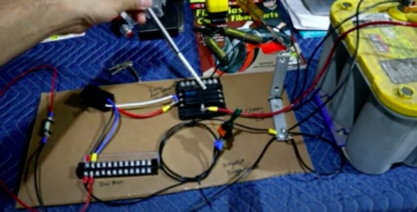
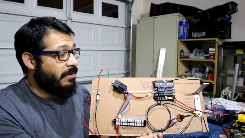
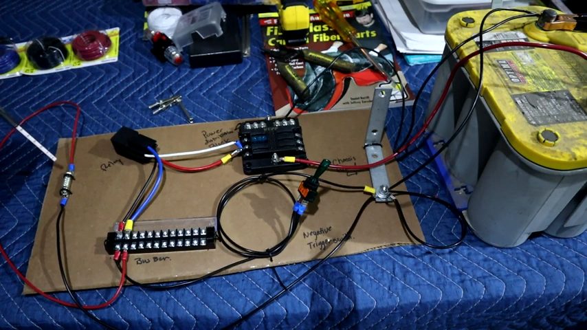
Step 2: Wiring Template or Diagram
I recommend using a template for the PDB wiring. You can use an online version. However, you may not have access to the exact diagram to wire all the components of the PDB appropriately. So, take a look at the one below:
Step 3: Establish Wire Codes
Adapting a conventional wire code for your PDB is helpful and necessary to limit potential confusion and disasters.
- The red wires should represent live or positive connections (pin 30 on the relay)
- The black wires should connect to ground connections (pin 85 on the relay)
- The blue wire represents power out (pin 87 on the relay)
- A white wire enables a negative trigger (pin 86 on the relay)
Step 4: Connect the PDB and the Inline Fuse (if you are not using a fused PDB)
First, use a wire stripper to remove the insulation coating of the red wire to about 1 inch deep to get enough conductive surface for the connection.
You can still torch the insulation sheath with a matchstick if you don’t have a wire stripper. Wait for the insulation coating to cool down (just for a few seconds, otherwise, you won’t be able to remove it), then strip it with your fingers. Remove the insulation coating from both ends of the red wire.
Now, attach the red wire to an alligator clip and connect it to the positive terminal on the battery. Attach the other end of the positive wire to the Power Distribution Block. The power distribution block is connected to an inline fuse.
The fuse in PDBs guards each piece of equipment. In the event of an electrical fault, the PDB blows up the fuse before any equipment starts a fire.
Step 5: Connect the Relay
Now, strip the insulation of another positive wire as before. Attach the inline fuse in the PDB and thread it to the relay station.
At the relay station, connect the relay terminals as follows:
Flip the relay to expose the numbered terminals at the bottom part.
Terminal or Pin 30
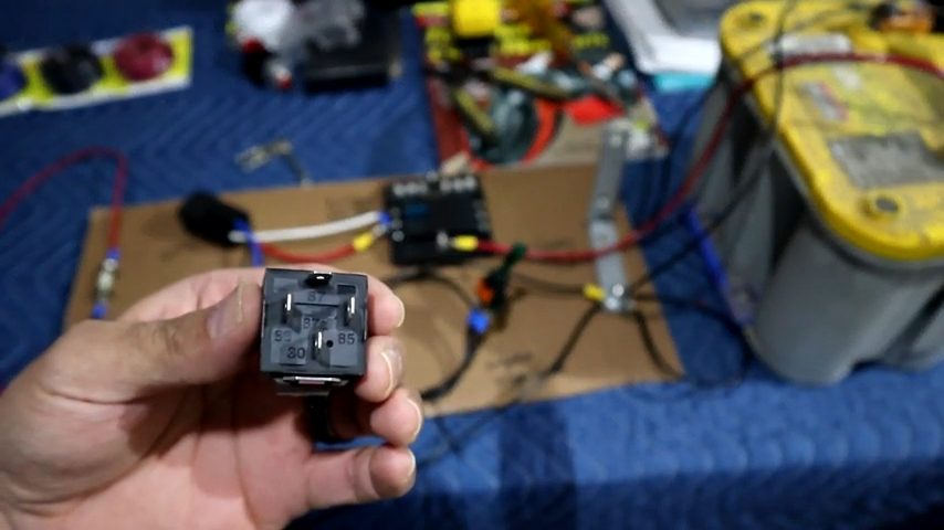
To this terminal, connect the positive wire from the PDB. It will connect the power from the PDB through the fuse and into the relay.
Terminal/Pin 87 (power going out)
Connect a blue wire, and strip the insulation to get enough conductive surface for connection. The blue line will represent the power going out. The blue wire should be situated right on the bump start nut line.
Negative Trigger – Pin 86
When doing a negative trigger, Ensure that pin 86 is connected to the power distribution block via a white cable. To do that, strip the white wire on both ends, attach it to pin 86 on the relay unit, and then connect it to the power distribution block. This way, you can switch the LED on and off (next step).
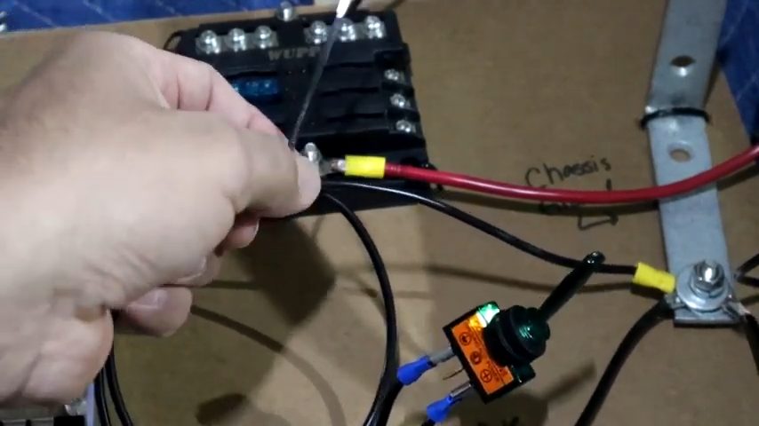
Ground or Black Wire Connection – Pin 85
Get a black wire, strip the insulation coating and connect one end to pin or terminal 85 on the relay unit. Attach the other end to the bus bar as shown below:
Next, thread the pin 85 connection from the bus bar to the trigger, then the chassis is connected to the negative terminal pm the battery.
Step 6: Complete the Chassis or Ground Connections
As aforesaid, the Chassis is linked to the battery’s negative terminal. Connect a black wire from the power distribution block to the chassis.
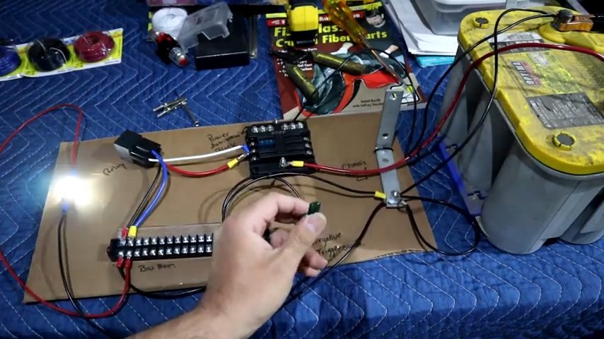
Step 7: Connect the LED Bulb
The LED bulb will help establish power flow through the PDB connection system.
So, run a black wire from the chassis to the appropriate terminal on the LED bulb. Then, locate the terminal where the blue wire is on the bus bar. On that terminal, link a red cable and thread it to the appropriate terminal on the LED bulb. That’s it, you have connected the PDB.
Step 8: Test the Negative Trigger PDB Connection
Testing is the easiest part. Toggle the switch on and off and observe the LED bulb behavior.
If the LED goes on and off accordingly, your PDB connection is a success.
Advantages of Using PDB
The following are some of the benefits of working using a PDB:
Easy Installation Process
It is not difficult to connect a PDB once you have a correct connection template or diagram.
It is Cheap and Saves Time
Connecting the PDB involves fewer wires than when using other connectors. Connecting multiple wires is not complicated, and it saves time.
Disadvantages of PDBs
Loosening of Wires
Experiments reveal that even the most secure connection can lose its grip on the block due to nudging forces or vibrations. That may result in serious problems. So, ensure you test all the connections before implementing the PDB. This way, you’ll know if the connections can endure the vibrational forces in various operating environments. (1, 2)
Limited Interior Applications
Power distribution blocks don’t have protective covers. They are not sealed against elements and cannot fit in many interior applications. So, always be certain about your interior applications before considering a power distribution block.
Take a look at some of our related articles below.
- Can I connect red and black wires together
- Is red wire positive or negative
- How to wire multiple lights to one cord
References
(1) vibrational forces – https://www.britannica.com/science/vibration
(2) environments – https://www.nationalgeographic.com/environment
Video Reference